Disclaimer and implied promise to keep the author harmless
This page is for informational purposes only. It comes with no warranty and the auther takes no responsibility of its correctness or usability for any application. Please do use it ONLY for educational purpose with the understanding that despite the care taken for correctness, it could contain errors and may not be suitable for any particular purpose. Readers of this article or any other article on this site EXPRESSLY agree to take full responsibility of their own actions holding the author(s) totally harmless and free of any liability. If you do not agree please do not continue reading any further.
Before we start
Here is what I gathered over time to build a car control. Most of the components are not used though in final build.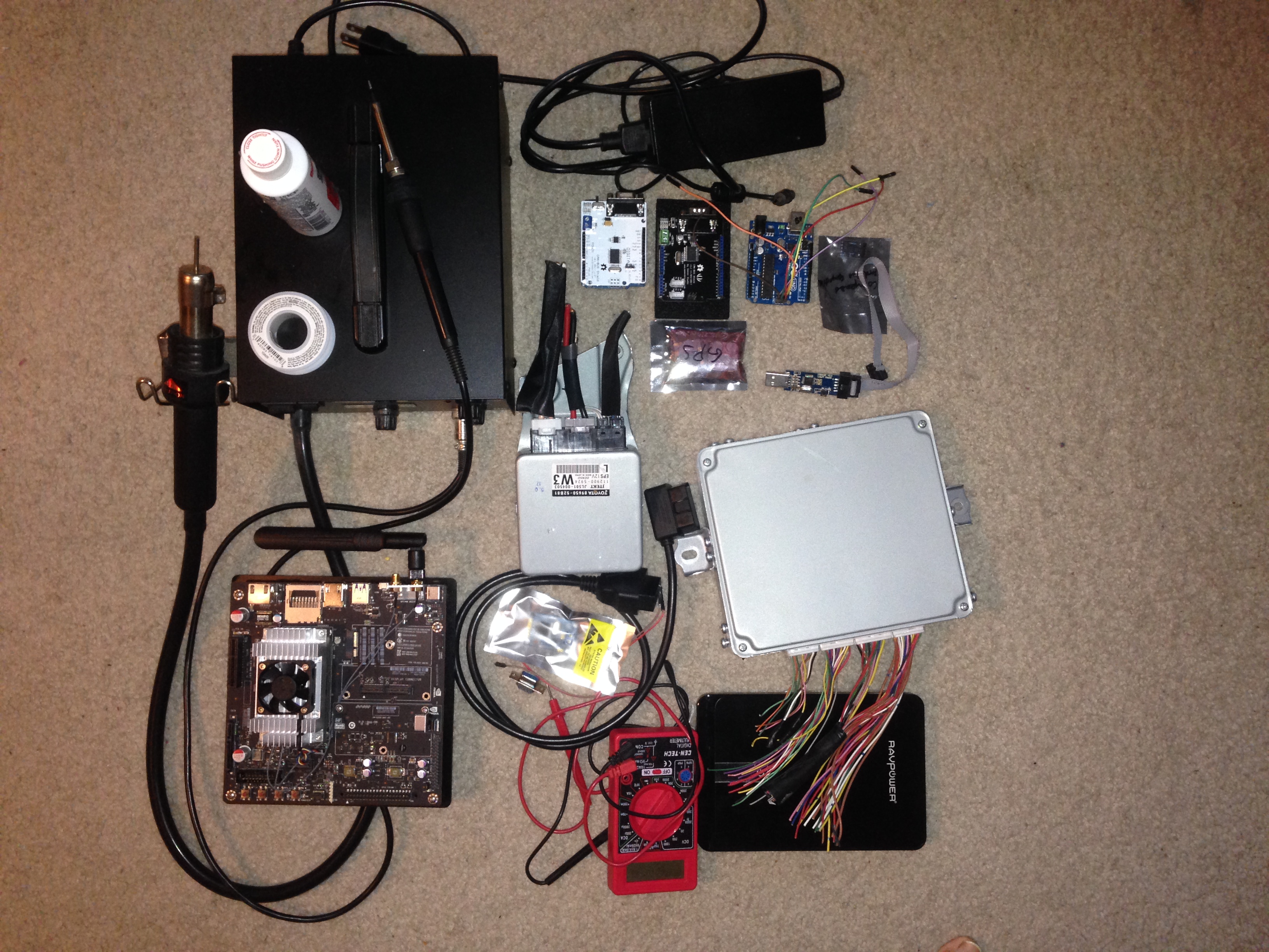
Car of choice
I have decided to use a Toyota Prius (it has to be red of course) as the base
car for the system.

The controller design
The Steering ECU receives toque signal voltage from the steering torque sensor. The amount of force applied by the person on the wheel is converted to a voltage and is sent to the Steering ECU as an analog signal.
The Toyota Prius (2017 model) torque sensor has 6 wires on the torque sensor. The
connector is labeled as z17 on the prius service manual (may get it from techinfo.toyota.com for a fee).
Torque sensor connector pinout
| Pin | Wire color | Operation |
| 1 | Blue | Torque signal 2 (T2) |
| 2 | White brown | Signal ground for T2 |
| 3 | Brown | Voltage source for T2 |
| 7 | Orange | Voltage source for T1 |
| 8 | White orange | Signal ground for T1 |
| 9 | Green | Torque signal 1 (T1) |
If you look at the pinout there are two torque signal pins (T1 and T2) on the connector. If there is no force applied on teh stering both pins send 2.5 volts. Resulting the difference between those to be zero.
If you apply a little force to turn the steering wheel the torque sensor will send different voltages on the torque signal wires. One will go up from 2.5v and another will go down from 2.5v. Which one will go up and which go down depends on the direction of the wheel rotation. If you try to rotate left T1 will go up and T2 will go down and if you turn right T2 will go up and T1 will go down (TODO: verify direction is correct).
For example if you turn left a little T1 may send 2.53v and T2 will send 2.47v. The difference between those are 0.06v and this difference is proportional to amount of force applied to the steering wheel.
When steering ECU detects that there is a voltage difference between T1 and T2 it will turn the power steering assist motor to help the driver turn the wheel with less effort than it would require without a power stering assist system.
We use this system to turn the wheel without any input from the driver on the steering wheel. We send correct voltage through T1 and T2 and the car ECU thinks (!) that the driver is turning the steering wheel and it powers the power steering motor which in turn rotates the wheel even though no force is applied to the physical stering.
Using components off an old car
Buying a car without knowing if it will work or not is a big risk. I would not be able to get another car if the first one did not work. So, I decided to spend about 200$ to buy parts from ebay to test my assumptions first.
The circuit
To make it simple I have designed a simple voltage divider using two 4.7K resistors and a
5K variable resistor (potentiometer) as shown below.
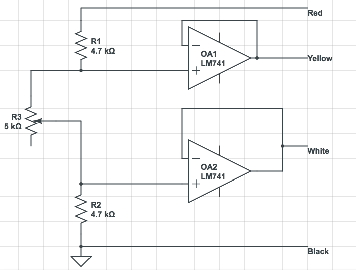
Since applying any load with simple voltage divider requires almost infinite input impedence I have used two LM741 op-amps as buffer which gives near infinite input impedence and near zero output impedence.
If we put put the potentiometer at zero ohm position (rotate leftmost position) the outputs (yellow and white wires) will give near 2.5v output. Changing the value of potentiometer will cause the outputs to have different voltage. The nice thing about this circuit is it will add a small amount to yellow and reduce same amount from white wire. This is exactly how it behabes when we rotate the steering wheel to the lect on real prius car.
Adding controller to the mix
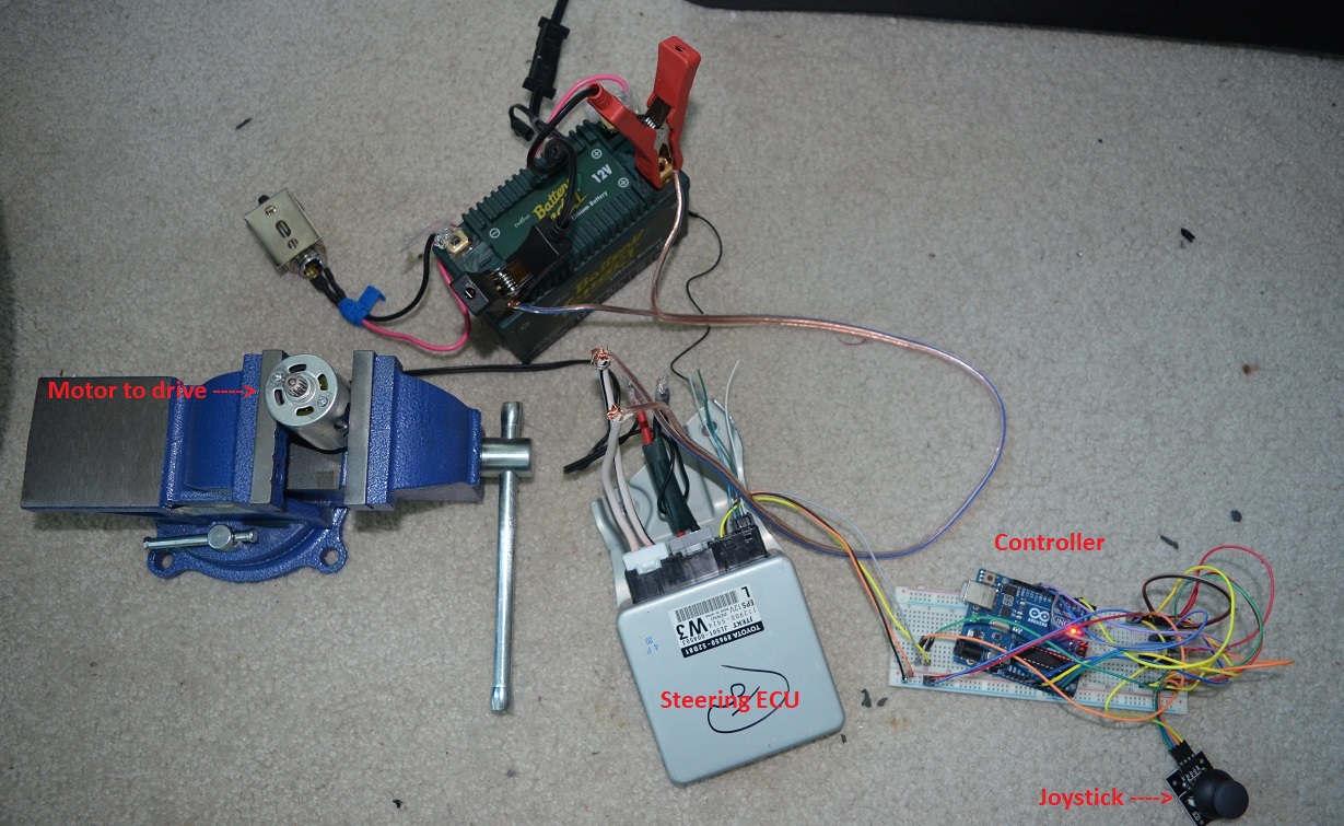
The simple voltage divider is great for a proof of concept. But we need a microcontroller to control the voltages on a real system. So, I have added a Arduino UNO and added a small joystick to control the motor.
TODO: Add the Arduino control code here.
Here is how it looks when I built the above initial design with a simple DC motor as output:
OK, thats basically it. If we build the system and add it to a real car we will be able to control the car using joystick. Is not that first step to make the car self driving?
Lets now move to the real car and show what I did not take this simple circuit to control the Prius (I used a different circuit than voltage divider - but thats just to make the system robust. I'll add the final complete circuit at the end of the article).
Looking through the window
As I was done with the design for the day I was near the window of my living room with a friend and after long day of tweaking things the moon looks so good:
OK, we can now go to work on the car in good mood.
Accessing the car system
Once we have the car we have to open the instrument panel to access the cars internal system.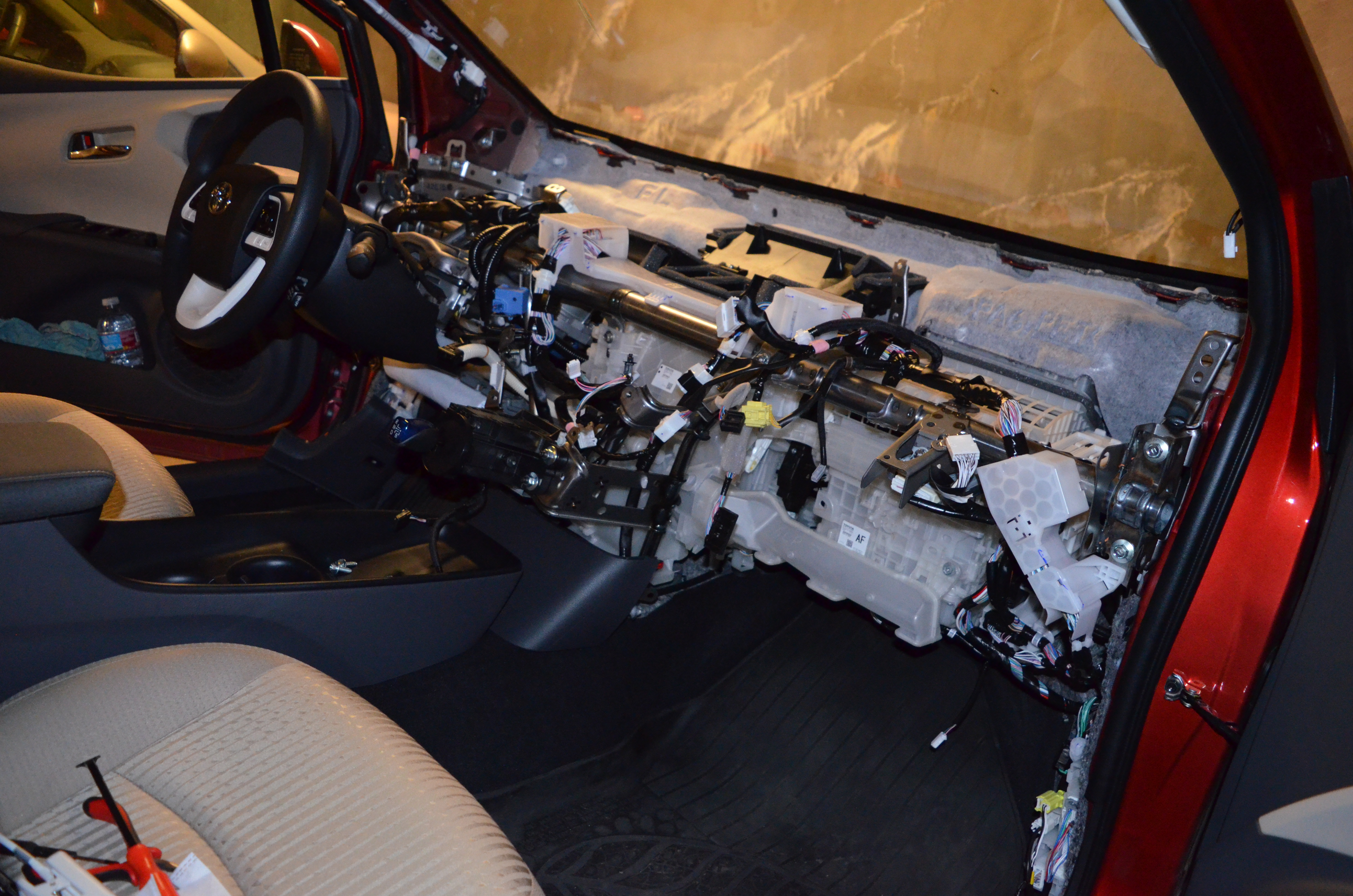
The steering torque sensor connector
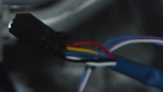
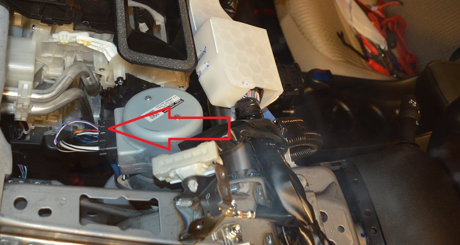
After opening the instrument panel we have to find the steering troque sensor connector.
It looks like this:
And here is how it looks when you disconnect it from the steering controller:
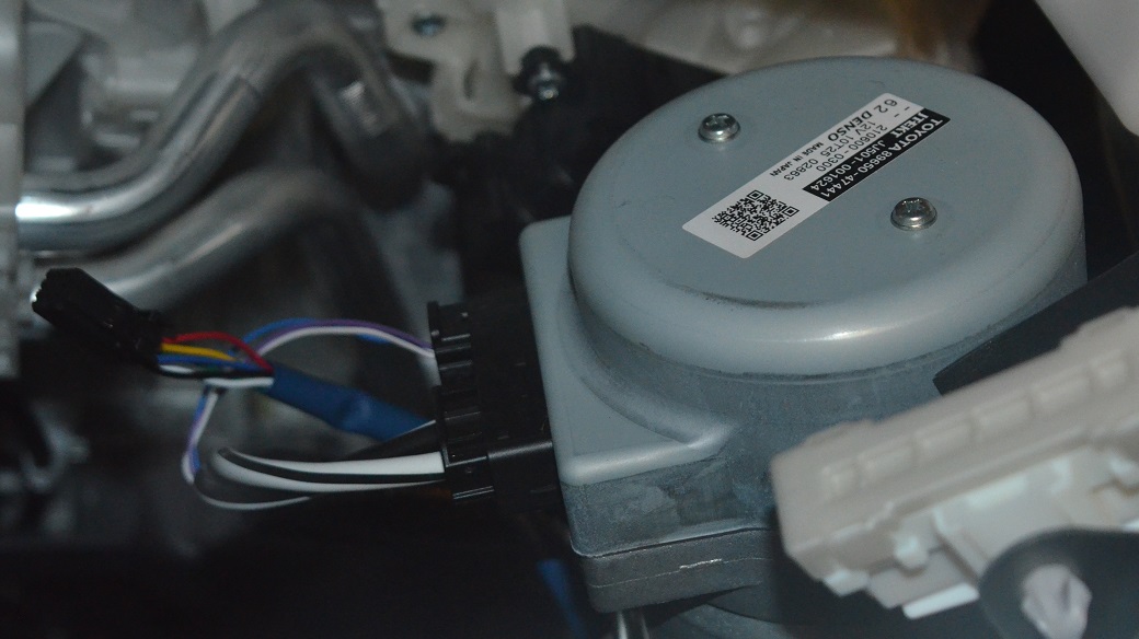
This is how it looks at this moment. I have cut the torque signal wires and all 4 ends goes to arduino A0, A1, A2, A3 pins. I am reading the signals from A0 and A1 which is coming from torque sensor and plan is to provide same signal back to the controller using A2 and A3 pins. I am hoping if I could capture the voltages and give same voltages back to the controller it should move/power the steering assist motor. If I do not put the arduino as pass through the motor is powered, but with arduino it still is not working. I am guessing its probably power issue or something. Will look into it over the weekend. When it works I'll just capture the torque values in both direction and will try to replay same values to see if the motor will be powered. Put the torque values in graph etc.
This is how it works with the joystick:This is the final result (a friend is helping with joystick and I am on drivers seat for safety reason):